
 ultimate-guide
Integrate Analog Hardware Into Digital Workflows
Table of Contents
- Why Integrate Analog Hardware Into Your Digital Workflow
- Hardware Insert Setup in Your DAW
- Managing Latency With Analog Outboard Gear
- Gain Staging Analog Hardware for Digital Recording
- Best Audio Interface for Hardware Inserts
- Signal Flow and Patch Bay Setup
- Real-Time Processing vs. Printing to Disk
- Troubleshooting Ground Loops and Hum
- Frequently Asked Questions
Last Updated: September 28, 2026
Why Integrate Analog Hardware Into Your Digital Workflow
To integrate analog hardware digital systems into your workflow bridges two sonic worlds, pairing the precision of digital audio workstations with the character and musicality that outboard gear brings to your mixes. This hybrid approach has become standard in professional mastering studios because it combines the best technical capabilities of both domains.
At LB-Mastering Studios, we've found that artists working with integrated analog-to-digital systems achieve richer, more translatable masters. Analog gear imparts harmonic distortion, compression characteristics, and dynamic range processing that digital plugins struggle to replicate authentically. When you integrate analog hardware into your digital workflow, you're adding musicality that translates across streaming platforms, headphones, and physical formats like vinyl.
The challenge most producers face is technical: latency, gain staging, impedance matching, and recall management create friction between your DAW and outboard gear. This guide walks you through the specific steps to set up a functional hybrid studio and capture the sonic benefits without the headaches.
Hardware Insert Setup in Your DAW
Setting up hardware inserts in your digital audio workstation requires careful attention to routing and I/O configuration. Most DAWs support hardware inserts through dedicated insert paths that send audio to your interface outputs and receive it back through inputs.
Configuring I/O Routing for Hardware Inserts
Your audio interface is the bridge between your DAW and analog gear. Assign specific outputs to your outboard equipment and create corresponding input channels to receive the processed signal back.
In your DAW's I/O settings, create a stereo pair of outputs labeled "Hardware Insert Out" and "Hardware Insert In." Route the output to your audio interface's physical outputs (typically XLR or TRS balanced connections), and set the input to receive from the corresponding interface inputs where your outboard gear's outputs connect.
The signal path should be: DAW track → hardware insert send → audio interface output → outboard gear input → outboard gear output → audio interface input → DAW track return. Any break in this chain causes dropouts or phase cancellation.
Test your routing with a short audio sample before committing to full mixes. Send a click track through the hardware insert and verify that audio returns cleanly without distortion or signal loss.
Setting Correct Buffer Size and Sample Rate
Buffer size and sample rate directly impact latency and audio quality when you integrate analog hardware digital systems into your workflow. Smaller buffers mean lower latency but higher CPU load; larger buffers reduce CPU strain but increase delay.
For mixing and mastering with hardware inserts, use a buffer size of 256 or 512 samples at 48 kHz sample rate. Ensure your audio interface, DAW, and any external clocking devices all run at the same sample rate, mismatches introduce artifacts and sync issues.
Managing Latency With Analog Outboard Gear
Latency is the delay between when audio enters your system and when it exits. With analog hardware in your signal chain, latency accumulates at multiple points: your audio interface conversion, cable transmission, outboard processing, and return conversion.
Calculating Round-Trip Latency
Round-trip latency is the total delay from your DAW output through the outboard gear and back to your DAW input. A typical audio interface might have 2-3 ms of latency on output and 2-3 ms on input, totaling 4-6 ms round-trip. Most analog units introduce minimal latency (under 1 ms), but some digital processors can add 5-20 ms.
Use your DAW's latency compensation tools to measure actual round-trip latency. Send a short click through your hardware insert and use a latency measurement plugin to determine the exact delay. Most professional DAWs include built-in latency measurement features in their preferences.
Applying Manual Latency Offset in Your DAW
Once you've measured round-trip latency, apply a manual offset to compensate. Your DAW's hardware insert plugin should include a latency compensation field where you enter the measured delay in samples or milliseconds.
If your measured round-trip latency is 8 ms, convert it to samples at your session sample rate. At 48 kHz, 8 ms equals approximately 384 samples. Enter this value in your DAW's latency offset field to keep everything phase-aligned.
Gain Staging Analog Hardware for Digital Recording
Proper gain staging ensures that analog gear operates in its optimal dynamic range while maintaining signal-to-noise ratio throughout your chain. Analog equipment is designed to work with specific input levels, pushing too hard causes distortion, while too-quiet signals expose noise floor issues.
Setting Input and Output Levels
Set your input level to the outboard gear so that peaks hit around -6 dB to -3 dB on the unit's meter. This headroom prevents clipping while allowing the gear to impart its characteristic coloration. Most analog compressors, EQs, and summing mixers sound best when operating with healthy input levels that drive the circuitry without exceeding the maximum input specification.
At your DAW, set the output level to the hardware insert so that the signal reaches the outboard gear at the correct input level. Start at -12 dB on your DAW fader and adjust upward while monitoring the outboard gear's input meter. On the return path, set the outboard gear's output level so that the signal returning to your DAW sits around -6 dB to -3 dB on your interface's input meter.
Avoiding Clipping and Noise Floor Issues
Clipping occurs when audio exceeds the maximum level your equipment can handle. Watch your outboard gear's output meter and ensure peaks stay within the green zone. Noise floor becomes audible when your signal is too quiet relative to the inherent noise of the analog equipment. Maintain healthy input levels to keep the signal well above the noise floor.
Test your gain staging with a variety of material, quiet vocals, loud drums, and mixed content. Each source may require slight adjustment to the input level while maintaining consistent output levels back to your DAW.
Best Audio Interface for Hardware Inserts
Your audio interface is the critical link between your DAW and analog gear. The best interface for hardware inserts prioritizes low-latency performance, accurate analog-to-digital and digital-to-analog conversion, and sufficient I/O count for your hardware setup.
Look for interfaces with at least four dedicated outputs and four inputs if you plan to use multiple hardware inserts simultaneously. Balanced XLR or TRS connections reduce noise and ensure proper impedance matching with professional outboard gear. Interfaces with built-in monitoring and latency compensation features simplify your workflow significantly.
Sample-accurate performance matters for phase-coherent mixing. Your interface should support sample-accurate I/O alignment so that the return signal from your hardware insert aligns precisely with your DAW's timeline.
Signal Flow and Patch Bay Setup
A well-organized signal flow prevents ground loops, reduces noise, and makes recall management straightforward. Your patch bay becomes the central hub where all connections route through dedicated normalized paths.
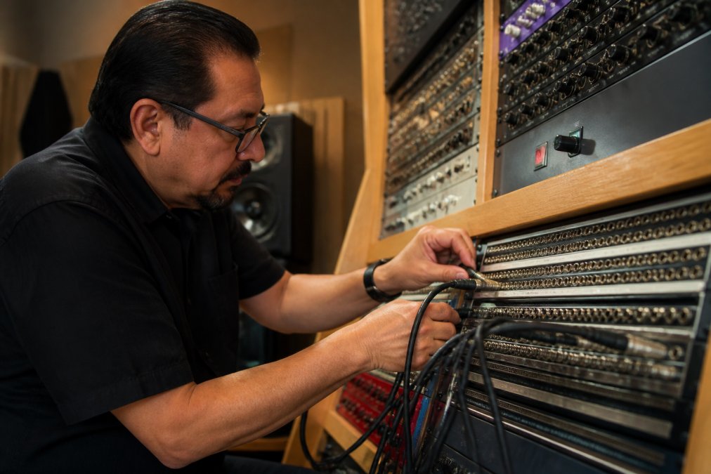
Normalization is the key to efficient patching. When a patch bay is normalized, the top row connects to the bottom row by default. Inserting a cable breaks the connection and routes the signal to your chosen destination. Create dedicated insert paths for each piece of outboard equipment and label everything clearly.
Use color-coded cables to distinguish between different signal paths: one color for hardware inserts, another for summing paths, and another for monitoring outputs. Ground loops occur when audio travels through multiple paths to ground, creating a 50 or 60 Hz hum. Minimize ground loops by ensuring that only one connection between your audio interface and outboard gear provides the ground reference. Use balanced XLR connections throughout your signal chain, they reject common-mode noise far better than unbalanced RCA connections.
Real-Time Processing vs. Printing to Disk
Real-time processing lets you hear your hardware processing as you work, while printing to disk commits the processed audio permanently to your DAW. Real-time processing is ideal during mixing when you want to experiment with different outboard gear or settings. Printing to disk locks in your processing choices and frees up your audio interface outputs for other tasks.
During mixing, work with real-time hardware inserts so you can A/B different settings and make adjustments.
Troubleshooting Ground Loops and Hum
Ground loop hum is a 50 or 60 Hz tone that appears when multiple ground paths exist in your signal chain. Identify it by listening for a low-frequency buzz underneath your audio, most noticeable during quiet passages.
Frequently Asked Questions
How do I manage latency when using analog outboard gear in a DAW?
Calculate your round-trip latency by measuring the time your signal takes to leave the DAW, pass through the audio interface, hit the outboard gear, and return. Most audio interfaces display this in milliseconds. Once you know the latency value, manually offset it in your DAW's delay compensation settings. This ensures your processed audio aligns perfectly with unprocessed tracks, preventing phase issues and timing problems during mixing and mastering.
What is the best way to calibrate analog levels for digital recording?
Start by setting your DAW output to -3dB to -6dB below clipping. Feed this signal into your outboard gear and adjust the input gain so the unit's meter reads around -12dB to -6dB on its scale, depending on the device's design. This leaves headroom for peaks. Return the processed signal to your audio interface input, aiming for -6dB to -3dB on the return. Use a reference tone at 1kHz to verify levels across your entire signal chain. Proper gain staging prevents distortion, maintains dynamic range, and maximizes the signal-to-noise ratio throughout your hybrid workflow.
Why is analog gear still relevant when digital tools can do the same thing?
Analog outboard gear introduces harmonic distortion and natural compression characteristics that many engineers find sonically desirable, especially in mastering. Digital tools offer precision and recall, but analog processing adds color and musicality that's difficult to replicate in-the-box. A hybrid workflow combines the best of both: you get the creative, organic qualities of analog processing alongside the flexibility, editing power, and recall management of digital audio workstations. This approach is why professional mastering studios continue to invest in high-end analog gear.